
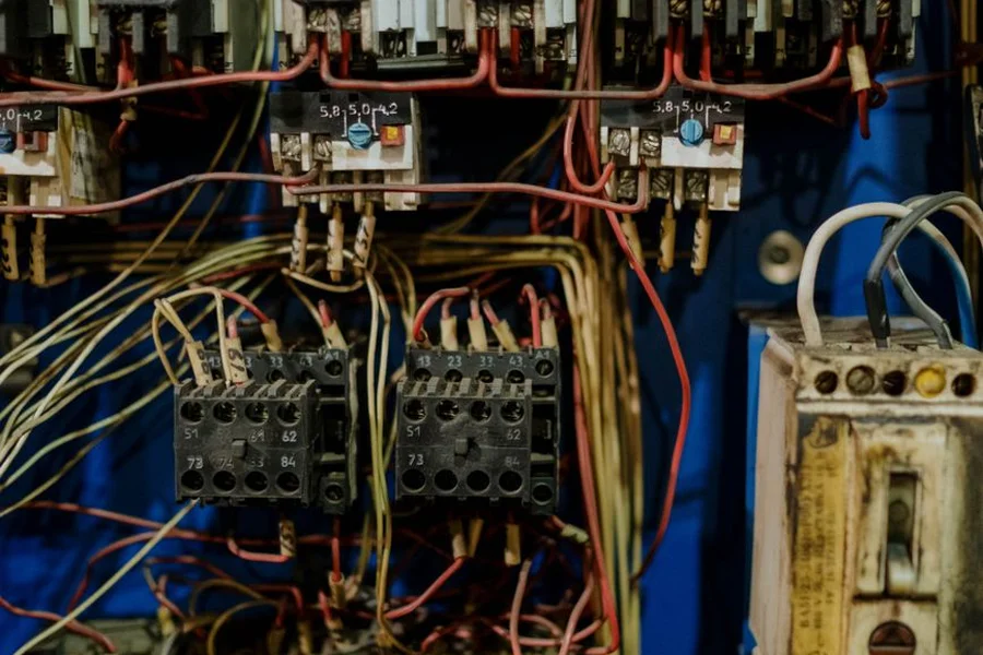
Boat Wiring Diagram: A Guide to Marine Electrical Standards
For boat owners, few projects are as intimidating yet essential as marine electrical work. The combination of salt water, constant vibration, humidity, and heat creates a highly hostile environment for copper and plastic. If your vessel’s bilge pumps fail, navigation lights go dark, or engine starting circuits cut out, the issue is almost always a corroded connection or a poorly routed wire. Understanding how to read, sketch, and follow a boat wiring diagram is the single best way to ensure safety, reliability, and ease of troubleshooting when you are out on the open water.
Whether you are rewiring a classic center console, adding modern GPS electronics to your helm, or simply trying to diagnose a persistent battery drain, following established safety guidelines is crucial. In this comprehensive guide, we explore the industry standards set by the American Boat and Yacht Council (ABYC), detailed wire color coding, key components of a marine electrical system, and tips for drawing a clean, custom wiring map.
The Critical Role of ABYC Standard E-11
Unlike residential home wiring or basic automotive electrical systems, marine systems require strict adherence to specialized standards. In the United States, the primary authority on this is the ABYC Official Website (American Boat and Yacht Council), which publishes **Standard E-11** for AC and DC electrical systems on boats. Following these codes is not just a matter of convenience; it is a critical fire-prevention safety measure, as faulty wiring is a leading cause of boat fires.
For professionals starting a new marine repair workshop or a broader construction business, complying with ABYC standards is essential for commercial insurance and liability. The harsh marine environment requires specialized components that differ significantly from automotive parts, ensuring every link in the circuit is corrosion-resistant and vibration-tested.
“Never use household solid-core wire or automotive terminals on a boat. The constant vibration of a hull will quickly fracture solid copper, while moisture will corrode un-tinned wires.”
Selecting the Right Materials for Marine Wiring
Before drawing your diagram, you must ensure you are using marine-grade materials. The key specifications every boat owner should verify include:
- Stranded, Tinned Copper Wire: Every strand of copper wire should be coated in tin. This thin tin layer prevents oxidation (corrosion), which turns raw copper into a green, non-conductive powder. Stranded wire also tolerates the structural flexing and motor vibration of a boat far better than solid wire.
- Marine-Grade Insulation: Look for wire rated as UL1426, which is designed to resist oil, fuel, battery acid, and temperatures up to 105°C (221°F) in engine compartments.
- Heat-Shrink Terminals: All connections should be made using crimp terminals that feature integrated heat-shrink tubing. Once crimped, heating the tubing shrinks it tightly around the wire’s insulation, sealing out moisture and salt.
For DIY boaters who enjoy restoring older vessels or modifying recreational vehicles, learning about marine systems is similar to studying specialized utility configurations, such as understanding the requirements for mobile housing or choosing the right rv insurance. For sourcing official replacement harnesses and schematics, visiting resources like Marine Parts Express provides access to manufacturer-approved parts catalogs.
ABYC Standard DC Wiring Color Codes
Using standardized wire colors is essential for quick diagnostic checks. If every wire under your dashboard is red or black, tracing a short circuit is nearly impossible. The ABYC defines specific colors for DC systems under 50 volts:
| Wire Color | Primary Function / Circuit | Notes & Safety Guidelines |
|---|---|---|
| Red | DC Positive (+) Feed | Must always be fused close to the battery. |
| Yellow or Black | DC Negative (-) Return | ABYC strongly recommends yellow to avoid confusion with AC black (hot) wires. |
| Green / Green w/ Yellow | Bonding / Safety Grounding | Protects metal fittings from galvanic corrosion. |
| Yellow w/ Red Stripe | Starter Solenoid Control | Runs from the ignition key switch to the starter motor. |
| Brown | Bilge Pumps & Alternator Charge | Very common in bilge pump float switch circuits. |
| Dark Blue | Cabin & Gauge Lights | Feeds backlighting for dashboard instruments. |
| Grey | Navigation Lights & Tachometer | Controls red/green bow lights and white anchor light. |
| Pink | Fuel Level Sender | Connects the fuel tank sender unit to the helm gauge. |
Key Elements to Include in Your Boat Wiring Diagram
A complete boat wiring schematic should map the entire path from the power source to the ground. Every circuit must include these core components:
1. The Power Source (Battery Bank)
Most boats feature a starting battery and a deep-cycle house battery. Your diagram should show these connected to a marine selector switch (1, 2, Both, Off). This allows you to isolate the starting battery, ensuring you always have enough power to crank the engine.
2. Overcurrent Protection (Fuses & Breakers)
Every positive wire must be fused. Place a main high-amperage fuse (such as an ANL fuse) within 7 inches of the battery switch, and route the wire to a fuse block or circuit breaker panel to distribute power to individual accessories. Properly sizing your fuses prevents wire overheating and potential fires.
3. Distribution Blocks (Busbars)
To avoid stacking multiple wires on battery terminals, use positive and negative busbars. A busbar acts as a central junction point, organizing all negative returns into a single heavy-gauge cable that routes back to the battery, which is just as important as the advanced electrical safety features found in modern cars for safe daily driving.
Steps to Design and Draw Your Custom Wiring Diagram
If you are rewiring your vessel, do not start cutting wires without a plan. Spend an afternoon sketching a clean diagram by following these steps:
- Inventory Your Electronics: List every accessory you need to power (bilge pump, stereo, VHF radio, fishfinder, navigation lights, USB chargers). Record their maximum amperage draw.
- Calculate Wire Gauge (AWG): Determine the round-trip distance from the power source to the accessory. Use a marine wire calculator to choose the correct wire size based on a maximum 3% voltage drop for critical gear and 10% for non-critical loads.
- Map the Physical Layout: Sketch the components as they sit physically in the boat (stern, console, bow). Draw the positive wires in red (or orange/purple accessory colors), negative returns in yellow, and indicate fuse sizes clearly on each positive feed.
Investing the time to map out your electrical layout ensures that when you embark on your boating travel experiences, you can enjoy peace of mind knowing that every connection is secure, standardized, and fully documented.
Frequently Asked Questions
Why does ABYC recommend yellow instead of black for DC negative wires?
Historically, black was used for DC negative. However, because black is also the standard color for the AC “hot” wire in marine shore power systems (120V), confusing the two can cause fatal shock hazards. Yellow is now the standard for DC negative to prevent this confusion.
What is the difference between marine wire and automotive wire?
Automotive wire uses bare copper, which quickly corrodes in wet environments. Marine wire uses individually tinned copper strands, which resist corrosion, and features a thicker, more durable insulation designed to withstand bilge water and oil.
Can I mix AC and DC wires in the same bundle?
No. ABYC standards prohibit mixing AC and DC wiring in the same conduit or bundle unless they are separated by a physical barrier or the AC wiring is enclosed in a separate sheath to prevent high-voltage AC from bleeding into low-voltage DC systems.
How close should a fuse be to the battery?
Every ungrounded (positive) wire must have overcurrent protection (a fuse or breaker) placed within 7 inches of the connection to the power source, unless the wire is contained in a protective sheath, in which case it can be extended up to 40 inches.

Written by Rosella
Rosella is a self-taught digital creator with a passion for breaking down tech, lifestyle, and everyday topics into simple, easy-to-understand content. Based in Youngstown, Ohio, she brings a curious, multi-disciplinary approach to writing, covering everything from the latest tech trends to practical life hacks and personal growth insights.
Her goal is straightforward: take complicated ideas and explain them in a way that actually makes sense, so every reader, whether a total beginner or someone more experienced, walks away having learned something useful. When she’s not writing, you’ll usually find her exploring new tools, sharpening her skills, or spending time with family.
Through this blog, Rosella aims to build a community centered on real, actionable insights rather than fluff, jargon, or filler content.
